
When multiple automatic bollards are installed across a vehicle entrance, they need to operate as a coordinated access control system rather than as unrelated individual devices. A single command may need to lower several bollards simultaneously to allow an authorized vehicle to pass, then raise them again to restore the physical restriction. Explore RICJ automatic bollard solutions for coordinated vehicle access control in commercial and high-security environments.
Behind this operation are the control box, electrical connections, drive mechanisms, position sensors, and any integrated access control or safety devices.
Understanding how these components work together helps project buyers plan a suitable system, identify possible points of failure, and determine what should be checked before installation.
1. The Control Box Coordinates the Bollards
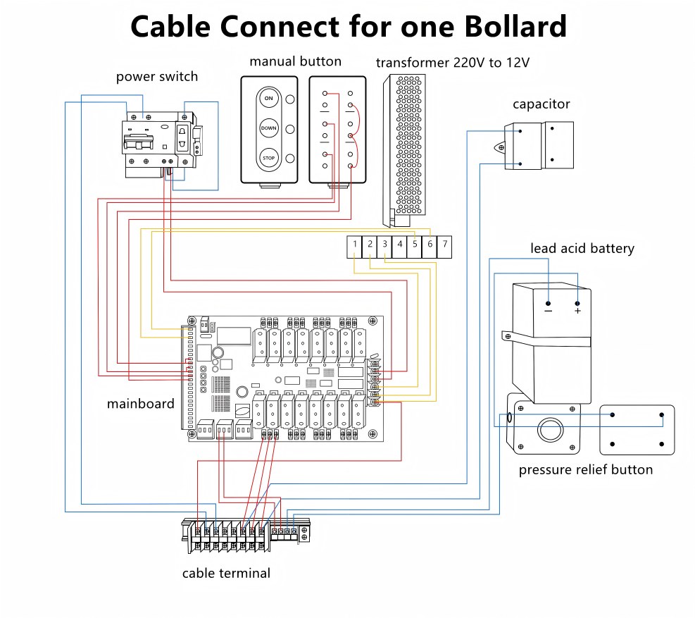
The control box acts as the central control point in many automatic bollard installations. It receives operating commands, processes available control and safety signals, and sends the appropriate instructions to the connected bollards.
Commands may come from a push button, remote control, access card reader, or an external access control system, depending on the configuration.
For example, when an authorized vehicle approaches a controlled entrance, the operator or access control system sends an opening command. The controller then activates the assigned bollards to lower them. Once the vehicle has passed, another command or the configured operating sequence initiates their return to the raised position.
The important point is that coordinated operation depends on the control logic and wiring configuration, not simply on installing several bollards in the same entrance.
2. How Multiple Bollards Operate in Coordination
A typical operating sequence can be understood in four stages:
Command → Control → Movement → Position Confirmation
-
Command: A user or connected access control device requests that the bollards rise or lower.
-
Control: The controller checks the configured operating logic and relevant safety inputs before issuing the movement command.
-
Movement: The connected drive mechanisms move the bollards according to the system design.
-
Position confirmation: Where position feedback is provided, limit switches or sensors report whether the bollards have reached their intended positions.
This feedback is important because issuing a command does not necessarily mean that every bollard has completed its movement. A properly configured system should provide the relevant status information or fault indication supported by its design.
Group Control vs Individual Control
Depending on the controller, bollards may support group commands, individual operation, or both.
| Control Mode | How It Works | Typical Application |
|---|---|---|
| Group control | Multiple assigned bollards respond to one command | Main entrances and controlled vehicle lanes |
| Individual control | A specific bollard can be operated separately | Maintenance, testing, or selected access points |
| Combined control | Group operation is available alongside individual commands | Sites with multiple entrances or different access requirements |
The number of bollards that can be controlled together varies by system. Project buyers should confirm the controller’s capacity, available inputs, and supported operating modes rather than assuming that every control box supports the same configuration.
3. One Controller Does Not Always Mean One Hydraulic Power Unit
The control arrangement and the hydraulic power arrangement are related, but they are not the same thing.
Some hydraulic installations use a shared hydraulic power unit to drive multiple bollards. Others use individual hydraulic units for each bollard while coordinating their operation through a common control system.
Both approaches can support coordinated access control, but their maintenance arrangements and failure characteristics differ.
| System Configuration | Main Characteristic | What to Consider |
|---|---|---|
| Shared hydraulic power unit | One power unit supplies multiple bollards | A fault in the shared unit may affect the connected group |
| Independent hydraulic units | Each bollard has its own hydraulic drive unit | A local hydraulic fault may be limited to one bollard |
| Centralized control with individual motor circuits | A controller coordinates multiple units | Circuit layout and fault isolation determine how failures affect the group |
The choice of drive system also affects installation and maintenance requirements. Read our guide to electric vs. hydraulic bollards for a closer comparison of these configurations.
The appropriate arrangement depends on the number of bollards, operating frequency, site layout, maintenance access, and required availability.
A shared power unit may simplify centralized equipment management, while independent units may help isolate certain local faults. Neither configuration is automatically better for every project.
4. What Happens if One Bollard Fails?
One of the key questions for facility managers is whether a fault in one bollard will stop the others from operating.
The answer depends on the system architecture.
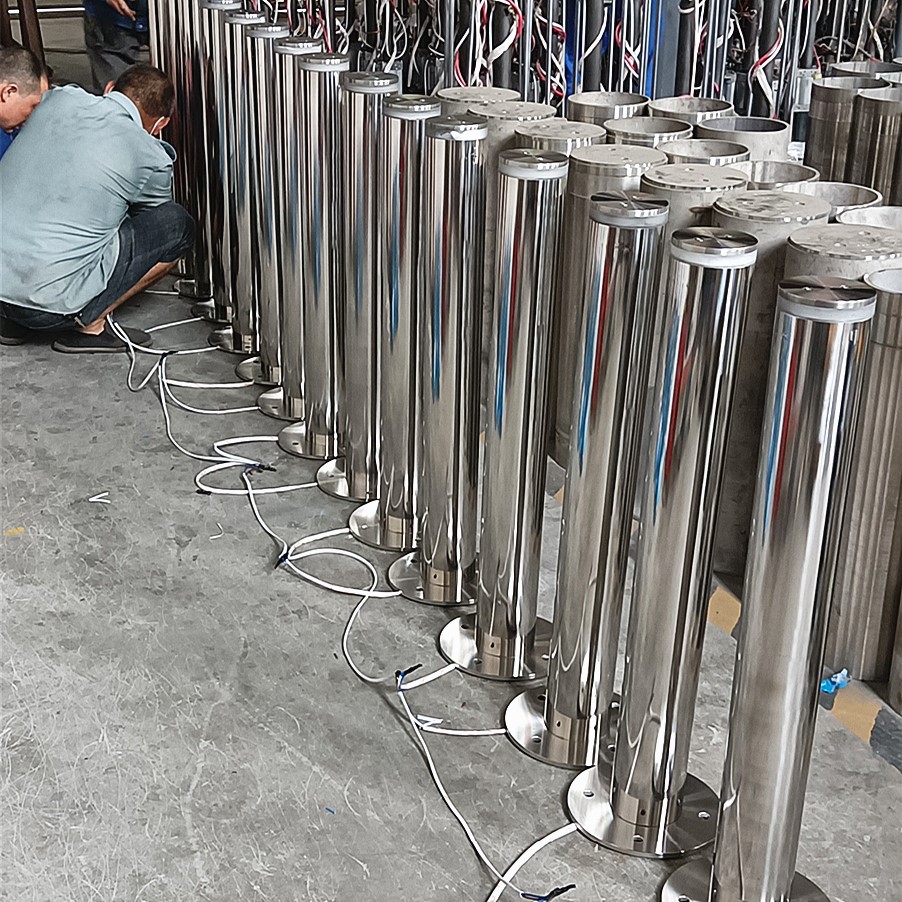
If each bollard has an independent motor circuit and the control system isolates faults appropriately, a local problem—such as a motor or mechanical fault—may not interrupt the operation of the remaining bollards.
However, independent circuits do not guarantee that every other bollard will continue operating under all conditions. A failure involving a shared controller, common power supply, or shared hydraulic power unit may affect several connected units.
How to Interpret Common Symptoms
| Observed Condition | Possible Area to Investigate |
|---|---|
| One bollard fails while the others operate normally | Local motor, wiring, position sensor, or mechanical obstruction |
| Several bollards stop responding together | Common power supply, controller, or shared control circuit |
| One bollard moves more slowly than the others | Local mechanical resistance or a drive-system problem |
| A command is received but a bollard does not reach its intended position | Position feedback, drive mechanism, or obstruction |
These symptoms provide starting points for diagnosis, not definitive fault identifications. The supplied wiring diagram and technical manual should be used to determine the actual cause.
For systems supporting independent operation, commissioning should also verify that a fault in one unit does not produce unexpected behavior in the others.
5. How Safety Devices Fit into a Multi-Bollard System
Coordinated movement is only one part of a reliable installation. Vehicle access systems may also need safety inputs and operating rules appropriate to their surroundings.
Depending on the project, these may include vehicle detectors, protective sensors, warning lights, audible signals, emergency controls, and interfaces with a building management or access control system.
For example, a vehicle detector can help identify a vehicle approaching or occupying a designated area. The controller’s programmed logic determines how that signal affects bollard movement. The presence of a detector alone does not guarantee that the system will respond safely in every situation.
Projects involving emergency routes or fire access require particular care. The required response to a fire alarm, power interruption, or system fault must be defined in the design and checked against the applicable local regulations.
Safety inputs, emergency operation, and failure behavior should therefore be agreed upon before the installation is commissioned, rather than added as an afterthought.
6. What Should Be Checked During Commissioning?
Before a multi-bollard installation enters regular service, the commissioning process should verify that the complete system behaves as intended.
The checks should cover:
-
Command response: Confirm that the supported buttons, remotes, or access control interfaces produce the correct operating commands.
-
Group operation: Verify that the assigned bollards respond according to the intended raising and lowering sequence.
-
Individual operation: Where supported, confirm that each unit can be tested independently.
-
Position feedback: Verify the expected upper and lower position indications and check for abnormal movement.
-
Safety functions: Test the specified detection devices, warning signals, and emergency operating procedures.
-
Fault response: Check the documented behavior when a unit, common power supply, or control component develops a fault.
RICJ provides factory testing and supporting technical documentation for its systems. On-site commissioning should then be performed by the client’s qualified technical team or the appointed installer according to the supplied configuration and instructions.
Factory testing supports product verification, but it does not replace checks of the completed installation, site wiring, safety interfaces, and operating logic.
Planning a Multi-Bollard Installation
The number of bollards is only one part of the design. Project buyers should also define the entrance layout, required control modes, hydraulic or electrical architecture, safety interfaces, and expected response to individual and shared-system faults.
A small entrance with two bollards may require a relatively simple control arrangement. A larger site with several entrances may benefit from separate operating groups, individual control, or integration with a broader access management system.
Defining these needs early helps ensure that the selected controller, drive units, wiring, and safety devices are compatible with the intended operation.
Coordinated Bollards Require Coordinated System Design
Multiple automatic bollards work together through a combination of control logic, electrical connections, drive mechanisms, and position feedback. Their ability to operate as a group—and their behavior when one unit fails—depends on the actual system configuration.
For facility managers, contractors, and system integrators, understanding these design choices helps with equipment selection, commissioning, and maintenance planning.
RICJ provides automatic bollard solutions for controlled vehicle entrances and project-specific access requirements. Contact RICJ to discuss a multi-bollard control configuration suited to your site layout and operating needs.
Post time: Oct-19-2026


